
Thermal Qualification Facilities
Please note that David-Florida Laboratory operations will be terminated by . Information related to this section may be consulted for reference purposes only.
The David Florida Laboratory (DFL)'s Thermal Qualification Facilities (TQF) comprise thermal vacuum chambers, thermal chambers and conditioners, specialty chambers, and various TQF-related support facilities. In addition, custom data processing applications are developed in-house to support these chambers and support facilities.
- Thermal vacuum chambers
- Thermal chambers and conditioners
- Specialty chambers
- TQF-related support facilities
- Custom data processing applications
Thermal vacuum chambers
TV1 chamber (1 × 1 m)
- This thermal vacuum chamber is used for the baking out of spacecraft subsystems and components
- Chamber size/working volume (horizontal cylinder): 1 m diameter × 1 m deep (3 × 3 ft)
- High vacuum: one turbomolecular pump capable of 1,100 litres/second nitrogen
- Pressure range (loaded): 1.3 E-3 to 1.3 E-5 Pa (1.0 E-5 to 1.0 E-7 torr)
- Temperature:
- Heating: ambient to +150 °C by eight 500 W infrared lamps
- Cooling: ambient to −50 °C by conductive plate
TV2 chamber (1 × 1 m)
- This thermal vacuum chamber is used for testing of spacecraft subsystems and components
- Chamber size/working volume (horizontal cylinder): 1 m diameter × 1 m deep (3 × 3 ft)
- High vacuum: one closed-loop cryogenic pump capable of 10,000 litres/second nitrogen
- Pressure range (loaded): 1.3 E-3 to 1.3 E-5 Pa (1.0 E-5 to 1.0 E-7 torr)
- Cooling capacity: 500 W
- Temperature: ±140 to −170 °C (+302 to −274 °F) in gaseous nitrogen mode
TV3 chamber (2.5 × 2.5 m)
- This thermal vacuum chamber is used for testing of spacecraft subsystems and modules
- Chamber size/working volume (horizontal cylinder): 2.5 m diameter × 2.5 m deep (8 × 8 ft)
- Turbo pump (helium leak testing): 1,500 litres/second (3,180 CFM)
- High vacuum: two closed-loop cryogenic pumps, each capable of 10,000 litres/second nitrogen
- High vacuum (loaded): 1.3 E-3 to 1.3 E-5 Pa (1.0 E-5 to 1.0 E-7 torr)
- Cooling capacity: 2 kW
- Temperature: ±150 °C (+284 to −220 °F) in gaseous nitrogen mode and −190 °C (−300 °F) in liquid nitrogen mode, as well a plate that can simulate the spacecraft deck (−120/+120 °C) while the rest of the chamber simulates the space environment (−190 °C)
TV4 chamber (1 × 2.5 m)
- This thermal vacuum chamber is used for testing of spacecraft subsystems and components
- Chamber size/working volume (horizontal cylinder): 1 m diameter × 2.5 m deep (3 × 8 ft)
- High vacuum: two closed-loop cryogenic pumps, each capable of 10,000 litres/second nitrogen
- Pressure range (loaded): 1.3 E-3 to 1.3 E-5 Pa (1.0 E-5 to 1.0 E-7 torr)
- Cooling capacity: 35 kW @ −120 °C (−184 °F)
- Temperature: +134 to −160 °C (+3273 to −256 °F) on shroud using a thermal conditioning unit
- Maximum ramp rate: 3 °C/min (5 °F/min) on thermal conditioning unit
TV5 chamber (7 × 10 m)
- This chamber is our largest thermal vacuum chamber and is used for testing of all-up spacecraft as well as subsystem and modules level testing
- Chamber working size (vertical cylinder): 6.7 m diameter × 10.7 m deep (22 × 35 ft)
- Working volume: 377 cubic m (13,300 cubic ft)
- Chamber access:
- Main access for personnel is through the 2.2 m diameter (7 ft) door
- Auxiliary access for personnel is through the 1.5 m diameter (5 ft) door
- Access for units under test is through the removable 6.7 m diameter (22 ft) top lid
- Internal staging is configurable to meet test requirements and is vertically adjustable
- Port sizes:
- 60 cm (24 in) port (1)
- 30 cm (12 in) ports (36)
- 20 cm (8 in) ports (12)
- Specimen supports:
- Bottom end-bell can support a maximum of 13,600 kg (30,000 lb) with a distributed load
- Bottom end-bell hard points that are isolated from the chamber (4): 6,800 kg load (15,000 lb) each up to a maximum of 27,000 kg (60,000 lb)
- Middle cylindrical section hard points (36): these hard points are located in six rings at different locations on the chamber wall and can support 4,500 kg load (10,000 lb) per ring up to a maximum of 13,600 kg (30,000 lb)
- Top lid hard points (8): 275 kg load (600 lb) each up to a maximum of 2,200 kg (5,000 lb)
- Thermal subsystems:
- Shroud construction: extruded aluminum
- Shroud surface properties: CAT-A-LAC black paint; (a>0.90 (lambda = 0.4 to 20 µm) at 22 °C (72 °F)
- Temperature: −190 °C (−310 °F) in liquid nitrogen mode
- Cooling capacity: 1.1 solar constants / 50% shroud area, load 260 kW maximum
- Cool down duration: from ambient to liquid nitrogen temperature in three hours (typical) after chamber is in high vacuum
- Warmup duration: from liquid nitrogen to ambient temperature in 12 hours (typical)
- Liquid Nitrogen Recirculation System (LNRS) provides closed-loop liquid nitrogen cooling to client equipment through six individual zones; pressure: 690 kPa (100 psig) maximum; and heat load: 50 kW maximum
- Vacuum subsystems:
- High vacuum: three closed-loop cryogenic pumps with isolation valves that are capable of 55,000 litres/second nitrogen (117,000 CFM)
- Pressure range in liquid nitrogen mode (loaded): 1.5 E-4 to 1.5 E-5 Pa (1.0 E-6 to 1.0 E-7 torr)
- Turbo pump: helium leak testing, 1,500 litres/second (3,180 CFM)
- Pump down duration: from ambient to high vacuum in eight hours (typical) including three pump/purge cycles
- Chamber venting duration: from high vacuum to ambient in three hours (typical) including three pump/purge cycles
Thermal chambers and conditioners
TP1 chamber (2.5 × 2.5 m)
- This chamber is used for thermal testing
- Foam box: 1.8 × 1.2 × 1.2 m (72 × 48 × 48 in)
- Temperature range inside the foam box: +120 to −120 °C (+248 to −184 °F)
Thermal conditioners
- Cooling capacity: 23.45 kW at −140 °C (−220 °F)
- Gaseous nitrogen flow rate: 960 litres/second (250 US gallons/second) with external static pressure of 5 cm (2 in) of water
- Heating capacity: 18 kW
- Working volume: 97 × 97 × 61 cm (38 × 38 × 24 in)
- Temperature control: ±1 °C (±2 °F)
- Temperature range: +150 to −150 °C (+300 to −240 °F)
- Ramp rate: up to 15 °C/minute (27 °F/minute)
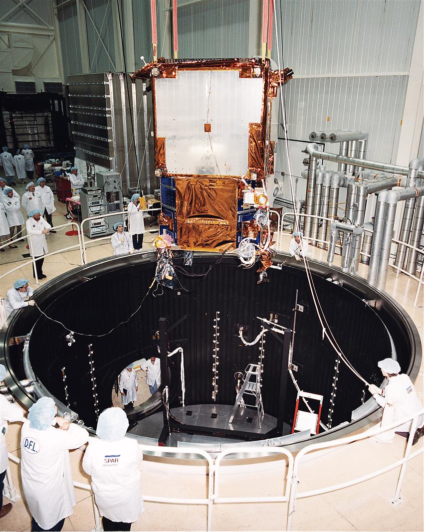
RADARSAT during thermal vacuum testing. (Credit: Communications Research Center Canada)
Specialty chambers
Temperature Altitude Chamber
- TA1 chamber (1 × 1 m)
- This chamber is used for temperature altitude testing. Temperature control is available for all virtual altitudes ranging from sea level to 12,200 m ASL (40,000 ft)
- Working volume: 0.96 × 0.93 × 1.07 m deep (38 × 36.5 × 42 in)
- Temperature range: +177 to −73 °C (+350 to −100 °F)
- Temperature maximum ramp rate: 3 °C/minute (5.4 °F/minute)
- Cooling capacity: 3 kW
- Altitude range: sea level to 35,052 m ASL (115,000 ft)
- Altitude maximum ramp rate: 25 m/second (5,000 ft/minute)
Temperature Humidity Chamber
- TH1 chamber (1 × 1 m)
- This chamber is used for temperature humidity testing
- Working volume: 1.02 × 1 × 1.17 m deep (40 × 39 × 46 in)
- Temperature range: +180 to −70 °C (+355 to −94 °F)
- Maximum ramp rate (heating): 6.2 °C/minute (11.2 °F/minute)
- Maximum ramp rate (cooling): 4.1 °C/minute (7.4 °F/minute)
- Cooling capacity at 0 °C (32 °F): 3 kW
- Humidity range: 10 to 98% RH
- Humidity control: ±2.5% RH
- Humidity uniformity: ±1.0% RH
- Full RH control is available from +7 to +88 °C (+45 to +190 °F)
TQF-related support facilities
Integration area within the TQF facilities specifications
- Crane: 23,000 kg (50,000 lb) gantry crane, 11 m (36 ft) hook height
- Floor area: 325 sq m (3,500 sq ft)
Large Area Pulse Solar Simulator
- The Large Area Pulse Solar Simulator system is a means of illuminating a large surface of a solar array to determine its performance characteristics (IV curve). This equipment consists of a control console and printer, lamp house, and pulse forming network.
- It requires a minimum floor area of 7 × 14 m (23 × 46 ft) when assembled
- It is capable of producing a 1.0 Solar Constant pulse
Surface property measurements
- Absorptivity/emissivity/reflectivity surface property measurements
Contamination monitoring
- Residual gas analysis
- Thermal quartz crystal microbalance
Testing support facilities
- Custom wiring facility
- Helium leak detection and testing
Thermal control systems
- Thermal Response and Power System (TRAPS): TRAPS supplies power (0 to 110 VDC) to infrared lamps and/or heater circuits. Voltages are manually set for every lamp or circuit up to 180 individually controlled ones.
- Automated Temperature Control System (ATCS): ATCS supplies power (0 to 110 VDC) to heater circuits (typical application). Voltages are computer-controlled; on an ATCS station, the operator enters temperature setpoints for each circuit, and ATCS maintains those setpoints by controlling the associated power supplies with up to 48 individually controlled circuits.
Custom data processing applications
DFL developed custom data processing applications give the technologist or computer operator access to their test or process information in a familiar visual and operational format and provide research and engineering personnel with detailed historical analysis and useful file management functions.
Thermal vacuum chambers – Combined Data Acquisition and Control System (CDACS)
- It is fully redundant and includes primary and redundant servers, as well as primary and redundant field control devices
- It can read up to 1,000 thermocouples
- The data viewer feature allows the viewing of data in the following formats: live bar graph, live chart, live spreadsheet, historical chart, and historical spreadsheet
- The console data server feature enables the broadcasting of logged data to client computers at regular intervals
- The thermal equilibrium feature automatically performs a running calculation of deltaT for given thermocouples to determine when stability criteria have been met
- The data relaying feature enables client telemetry to be sent to CDACS at regular intervals and become integrated into the CDACS database
- The virtual channels feature enables thermocouples, data relaying, or other channels to be read into CDACS and have calculations performed on them. The results of these calculations are output as virtual channels for subsequent analysis in real time if needed
- The data redundancy feature copies the CDACS database to a remote computer, and it does so once every minute for the duration of the test
All other chambers – Other Data Acquisition and Control System (ODACS)
- The ODACS data viewer feature allows the viewing of data in the following formats: live bar graph, live chart, live spreadsheet, historical chart, and historical spreadsheet
- On most chambers, e.g. the thermal conditioners and the TH1 Chamber (1 × 1 m), on-board controllers allow for the programmed operation of those chambers
- On all chambers that do not use nitrogen (e.g. TH1 Chamber (1 × 1 m), TA1 Chamber (3 × 4.3 m) can operate unattended for extended durations