
Radio Frequency Qualification Facilities
Please note that David-Florida Laboratory operations will be terminated by . Information related to this section may be consulted for reference purposes only.
The Radio Frequency Qualification Facilities (RFQF) comprises the:
The RFQF's measurement controllers and systems are connected to a secure David Florida Laboratory (DFL) local area network. Comprehensive third third-party and in-house measurement software products are used for reliable data acquisition, instrument control and data evaluation.
Antenna test facilities
The antenna test facilities comprise the Antenna Test Facility 1 (ATF1), Antenna Test Facility 2 (AFT2), Cylindrical Near-Field Facility (CNF), and Spherical Near-Field Facility (SNF). These anechoic chambers are used to evaluate the far-field performed characteristics of client-supplied antennas.
Antenna test facility 1 (ATF1)
Note: this facility is currently reserved long term and therefore not available to clients until at least .
- Capabilities: radio frequency (RF) testing for system, subsystem, and component level
- Frequency range: 1 GHz to 20 GHz
- Absorber reflectivity: from −25 dB at 1 GHz to −50 dB at 6 GHz and above
- Chamber size (L × W × H): 6.1 × 6.1 × 6.1 m (20 × 20 × 20 ft)
- Chamber door size (W × H): double leaf, 3 × 6.1 m (10 × 20 ft)
- Crane: monorail hoist, rated capacity 226 kg (500 lb)
- Azimuth/elevation/azimuth positioner: Scientific Atlanta 5524
- Indoor range: 5.6 m (18 ft) using 3 m (10 ft) pyramidal horn
Antenna Test Facility 2 (ATF2)
- Capabilities: RF and EMC testing for satellite, system, subsystem, and component level
- Near-field spherical measurement type: Theta-Phi
- Frequency range: 250 MHz to 40 GHz
- Absorber reflectivity from −25 dB at 250 MHz to −50 dB at 6 GHz and above
- Quiet zone measured reflectivity, worst case performance:
- Typical 10 m separation:
250 MHz: −20 dB
500 MHz: −26 dB - Maximum 13 m separation:
250 MHz: -15 dB
500 MHz: −21 dB
1 GHz: −29 dB
6 GHz and above: −50 dB
- Typical 10 m separation:
- Chamber size (L × W × H): 24 × 12 × 20 m (80 × 40 × 65 ft)
- Chamber access (W × H): 6 × 13.7 m (20 × 45 ft), double-leaf doors 3 × 10.7 m (10 × 35 ft) with four overhead panels 3 × 3 m (10 × 10 ft)
- Bridge cranes (2): 10 ton (22,000 lb)
- Antenna test tower: orbit L-bracket, 6 m (20 ft) high; maximum radial clearance 5 m (16 ft)
- Probe tower: 6 m (20 ft) high; three axes (roll/azimuth/elevation) on mobile heavy-duty air platform
- Indoor range: maximum 13 m (43 ft)
- High-performance network analyzer
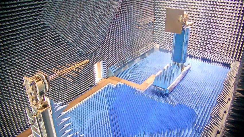
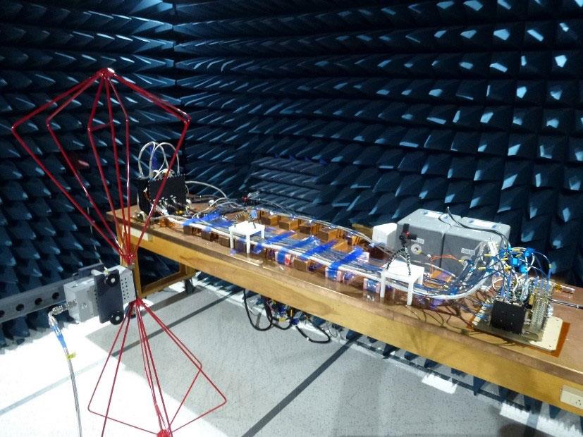
ATF2 Anechoic Chamber Configuration for 400 MHz Gain Standard. (Credit: Canadian Space Agency/David Florida Laboratory)
Cylindrical Near-Field Facility (CNF)
- Capabilities: RF near-field testing for system, subsystem, and component level
- Near-field cylindrical measurement type: Az-Y
- High-speed receiver system up to 20 GHz: NSI
- Chamber size (L × W × H): 6.1 × 6.1 × 6.1 m (20 × 20 × 20 ft); walls lined with absorber
- Absorber reflectivity: from −25 dB at 750 MHz to −50 dB at 6 GHz and above
- Bridge crane: 5 ton (11,000 lb)
- Cylindrical near-field scanner: NSI, 3.7 m (12 ft)
- Y-axis (probe): NSI-SC-5621
- Theta (azimuth): NSI
- Pol-axis (probe): NSI-SC-5631
- Open-ended waveguide (OEWG) probe assemblies up to 40 GHz
Spherical Near-Field Facility (SNF)
- Capabilities: RF near-field testing for system, subsystem, and component level
- Near-field spherical measurement type: Theta-Phi
- High-speed receiver system up to 50 GHz: NSI
- Chamber size (L × W × H): 7.3 × 4.9 × 3.6 m (24 × 16 × 12 ft)
- Absorber reflectivity: from −30 dB at 1 GHz to −50 dB at 6 GHz and above
- Antenna test tower: L-bracket, maximum radical clearance 1 m (3.2 ft)
- Theta (azimuth), NSI-SC-5838 (RT500)
- Phi-axis (roll), NSI-SC-5635 (RT300)
- Pol-axis (probe), NSI-SC-5633 (RT150)
- Probe assemblies up to 50 GHz
- Indoor range: 3.8 m (12.5 ft)
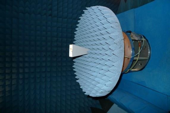
SNF Anechoic Chamber Configuration for Gain Standard Measurements. (Credit: Canadian Space Agency/David Florida Laboratory)
Electromagnetic Compatibility (EMC) Facility
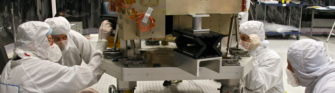
The EMC Facility's shielded anechoic chamber and anteroom are used to perform electromagnetic compatibility tests according to recognized standards on client-supplied devices such as satellites, satellite payloads, avionics equipment, and equipment for military application.
Typical Test Setup in the EMC Test Chamber (Credit: Canadian Space Agency/David Florida Laboratory)
- Capabilities:
- Radiated emission: 30 Hz to 40 GHz
- Conducted emission: 20 Hz to 500 MHz
- Radiated susceptibility: 30 Hz to 40 GHz
- Conducted susceptibility: 20 Hz to 400 MHz
- Testing standards:
- MIL-STD-461
- MIL-STD-462
- RTCA/DO160 (Except Lightning)
- DEF-STAN 59-41
- IEC 1000-4-2 (ESD), 30 kV
- SSP 30237/30238 (International Space Station)
- Test chamber overall size (L × W × H): 4.9 × 5.5 × 3.6 m (16 × 18 × 12 ft); shielded room lined with 24 in absorber
- Test chamber access door size (W × H): 1.8 × 2.1 m (6 × 7 ft)
- Ante-chamber overall size (L × W × H): 4.9 × 2.4 × 2.4 m high (16 × 8 × 8 ft); shielded
- Ante-chamber access door size (W × H): 0.91 × 2.1 m (3 × 7 ft)
- Copper ground plane size (L × W): 3.4 × 0.76 m (11 × 2.5 ft)
- Chamber shielding: calibrated according to IEEE-299-1997
- Deliverable documentation: formal reports according to MIL-STD-831
- EMC Receiver with FFT measurement capability. Scanning for very low emission limits, at reduced RBW, is much faster, compared with conventional scanning method, reducing the testing duration substantially.
- Professional Electromagnetic emissions and susceptibility measurement software
- Power lines availability:
- 15 Amp, 115 Volt, NEMA 5-15R: multiple
- 20 Amp, 120/208 Volt 3-Phase Y, NEMA L21-20R, 4P, 5W: multiple
- 30 Amp, 125 Volt, NEMA L5-30R, 2P, 3W: multiple
- 30 Amp, 120/208 Volt 3-Phase Y, NEMA L21-30R, 4P, 5W: multiple
- 60 Amp, 120/208 Volt 3-Phase Y, ARKTITE AH560R9W, 4P, 5W: two
- Power line filters (AC power): 100 dB attenuation, 10 kHz to 10 GHz

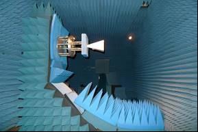
M3MSat – Testing in an anechoic chamber at the DFL in Ottawa. (Credit: Defence Research and Development Canada)
360 videos of the Radio Frequency Qualification Facilities
Explore further
- Date modified: